

Aluminum Housing CNC Machining: 5-Axis, Mill-Turn, or Cast-to-Machine?
Choose the process from the housing’s dominant geometry, functional datum relationships, and expected production volume—not from the machine name alone. Five-axis milling is usually strongest for prismatic housings with multi-face features; mill-turn is strongest when a stable rotational axis dominates; conventional machining can be economical when critical features do not cross setups; and a cast-to-machine route becomes credible only after tooling, casting variation, machining allowance, and volume are evaluated together.
Key Takeaways
- Start with the mounting, sealing, bearing, and port relationships that must remain stable after the part is unclamped.
- Match 5-axis to multi-directional access and mill-turn to a dominant bore, diameter, or flange axis.
- Keep conventional multi-setup machining in the comparison when geometry is orthogonal, fixtures are repeatable, and critical relationships can be finished from common datums.
- Calculate a project-specific casting break-even point and validate machining allowances.
- Define the inspection datum alignment, measurement method, and report requirements before requesting quotes.
Begin With Geometry and Function, Not Machine Capability
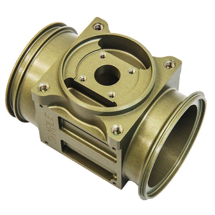
A complex housing may combine a deep cavity, cylindrical ports, sealing grooves, threaded holes, mounting ears, and machined faces. This creates access complexity, which affects tool reach and rigidity, and relationship complexity, which affects the position and orientation of features relative to one another.
Identify the geometry that controls function. A central bore may suggest turning, but prismatic cavities can still make the part milling-dominant. A block-like exterior may suit mill-turn when bearing seats, sealing diameters, and flange faces share one axis.
An experienced CNC machining service should be able to translate those relationships into a blank strategy, setup sequence, workholding concept, finishing plan, and inspection method before committing to production.
Use the following table as a screening tool, not as an automatic process assignment.
| Process Route | Best-Fit Geometry | Main Advantage | Main Limitation | Decision Trigger |
|---|---|---|---|---|
| 5-axis CNC milling | Prismatic body with features on several faces or compound angles | Reduces reorientation and improves access with shorter tools | Higher programming, simulation, and machine-hour requirements | Critical features span multiple directions and should remain in one datum-controlled setup |
| Mill-turn machining | Rotationally dominant body with added flats, ports, holes, or pockets | Turns concentric features and mills secondary geometry in one platform | Workholding and machine envelope may not suit large asymmetric housings | A bore, OD, or flange axis controls most functional relationships |
| Conventional multi-setup CNC | Orthogonal geometry with accessible faces and separable tolerances | Broad equipment availability and potentially lower hourly rates | Datum transfer and fixture repeatability add cumulative risk | Critical features can be grouped by setup without breaking functional relationships |
| Casting plus finish machining | Stable geometry with repeat demand and substantial removable stock | Near-net blank can reduce material removal per part | Tooling, casting variation, porosity risk, and design-change cost | Validated demand can amortize tooling and critical surfaces can receive reliable machining allowance |
Use a Function-to-Process Decision Hierarchy
A useful process decision starts with function and moves toward equipment, not the other way around. First identify the surfaces and axes that locate the housing in the assembly. Next identify the features that create sealing, bearing support, fluid or optical alignment, fastener preload, or service access.
Only then should the team compare machine types.
The following decision hierarchy prevents a common procurement mistake: selecting the route with the most impressive equipment list while leaving the critical feature relationships undefined.
- Define functional interfaces. Mark mounting faces, locating bores, bearing seats, sealing lands, port axes, clocking features, and assembly-clearance zones.
- Rank critical relationships. Determine which feature-to-feature relationships would cause leakage, misalignment, binding, vibration, or assembly failure if they moved.
- Group finish operations. Place related critical features in the same finishing condition wherever practical.
- Check workholding and tool access. Confirm that the proposed fixture supports the part without blocking the tools or deforming compliant areas.
- Check inspection access. Make sure the selected datum system and feature geometry can be reproduced during measurement.
- Compare total manufacturing cost. Include setup, programming, machine time, tooling, fixtures, finishing, inspection, expected quality risk, and design changes.
This hierarchy may reveal that different phases need different routes. A five-axis billet route may be appropriate during design validation because it avoids production tooling and supports rapid revisions. A cast blank with finish machining may become attractive later, but only after the geometry, alloy, demand, machining allowances, and inspection plan are stable.
Procurement teams should therefore request a process concept, not only a unit price. The concept should explain the proposed blank, operation sequence, setup count, datum transfer, critical finishing groups, inspection stages, and major assumptions. Two quotations that use different assumptions about inspection, surface treatment, or blank quality are not directly comparable.
Build the Datum Strategy Before Comparing Quotes
Machine selection cannot rescue an ambiguous drawing. A supplier needs to know which surfaces locate the housing in the assembly, which bore guides or supports another component, which face compresses a seal, and which feature clocks angular orientation.
A functional datum frame might use a mounting face as datum A, a main bore axis as datum B, and a clocking feature as datum C. The correct order depends on assembly constraint.
ASME Y14.5-2018 and ISO 1101:2017 support communication of geometric requirements, while ISO 5459:2024 addresses datums and datum systems. Apply the selected standard consistently.
Separate Size From Geometric Control
A bore-size tolerance does not control the bore’s position or orientation, and flatness on a sealing face does not define its relationship to a mating bore. Apply position, perpendicularity, profile, or runout only where function requires it and relate the control to functional datums.
This makes quoting more meaningful. The manufacturer can then design a setup and inspection plan around the same coordinate system used by the product engineer, instead of treating each dimension as an isolated pass/fail value.
Avoid Uncontrolled Tolerance Accumulation
If two ports are machined in different setups, their relationship depends on datum quality, fixture location, probing, calibration, and part stability. Five-axis or mill-turn can shorten this chain, but “one setup” still requires stable workholding, accessible finishing paths, and alignment that survives unclamping.
The practical question is not “How many axes does the supplier have?” It is “Which critical-to-quality features are finished from the same stable datum condition, and how will that condition be reproduced during inspection?”
Convert Functional Relationships Into Finish-Operation Groups
A drawing may contain dozens of dimensions, but only a smaller set normally controls the highest manufacturing risk. Build a critical-to-quality map that connects each requirement to its manufacturing and inspection condition.
For example, a sealing face and a locating bore may need to be finished after the same datum structure is established because their perpendicular relationship affects seal loading. Two opposing ports may need a common coordinate alignment because their axes guide an inserted assembly. Mounting-hole position may be less sensitive if the holes have assembly clearance and do not locate the product.
The process planner can then create finish-operation groups:
- Group the primary bore, related bearing seat, and reference flange when they share a rotational axis.
- Group sealing faces, groove locations, and adjacent locating features when seal compression depends on their relationship.
- Group cross-ports and multi-face holes when their axes must intersect or maintain a controlled orientation.
- Separate noncritical clearance holes, cosmetic pockets, and service features when datum transfer does not threaten function.
This grouping often matters more than the nominal setup count. Three controlled setups with stable common datums can be safer than a nominal one-setup route that requires long flexible tools, weak clamping, or inaccessible inspection.
When 5-Axis Milling Is the Strongest Route
Five-axis milling often fits housings with multi-directional ports, angled faces, deep pockets, and geometric controls crossing those faces. Indexed 3+2 machining may be enough for fixed orientations; continuous five-axis motion is more relevant for blended surfaces, changing tool angles, or interference avoidance.
The process can reduce re-clamping and orient the part for shorter, more rigid tools. It does not guarantee tolerance or finish: machine kinematics, fixture stiffness, tool length, cutting strategy, thermal condition, and inspection still matter.
Lynhow’s current public 5-axis milling page lists a maximum machining size of 950 × 650 × 650 mm, machining accuracy of ±0.01 mm, surface roughness of Ra 0.8 μm depending on material, and a minimum feature size of Ø0.50 mm. These values describe a published capability range, not an automatic commitment for every feature of a complex housing. A drawing review is still required to confirm geometry, datum access, local tolerance, and inspection conditions.
Choose 5-axis milling when:
- several critical ports, faces, or holes must be located from one datum system;
- tilting the workpiece provides shorter tool reach into a cavity;
- the housing is primarily prismatic rather than rotational;
- reducing manual setup transfers has more value than minimizing machine hourly rate; and
- the supplier can simulate tool, holder, spindle, fixture, and part clearance.
Decide Whether Indexed or Simultaneous Five-Axis Motion Is Required
Not every five-axis housing needs continuous five-axis cutting. Indexed 3+2 machining rotates the workpiece to a fixed orientation and then performs conventional milling. It is often effective for angled ports, bolt patterns on several faces, and cavities that need a more favorable tool angle.
Simultaneous five-axis motion becomes more relevant when the tool orientation must change during the cut. Examples include blended freeform surfaces, undercut access, collision avoidance around a complex envelope, or maintaining a controlled tool contact condition on a curved surface.
This distinction affects programming, simulation, machine time, and verification. Requiring simultaneous motion where indexed machining is adequate can add cost without improving the functional result. Conversely, treating a collision-sensitive freeform feature as simple indexed work can create access problems or force inefficient tool extensions.
Ask the supplier to identify which features use indexed positioning and which require continuous motion. The answer should connect directly to geometry and tolerance, not to a generic claim that five-axis machining is more advanced.
Control the Risks That Five-Axis Does Not Remove
Five-axis equipment reduces some datum-transfer risks, but it does not remove deformation, tool deflection, thermal drift, calibration error, or fixture movement. A tall housing held at one end may still behave like a flexible structure.
A deep port may still require a long boring tool. A sealing land may still move after a large cavity is opened.
For critical features, request the planned finishing condition and verification point. A robust concept may rough major cavities first, retain temporary support stock, re-establish the datum condition, and then finish the sealing and alignment features. In-process probing can confirm stock location or detect drift, but final acceptance may still require independent measurement after the part is released.
Do not select it solely because the part looks complex. A fourth-axis indexer or qualified two-operation fixture may be more economical when tolerance relationships allow it.
When Mill-Turn Machining Is the Better Fit
Mill-turn becomes compelling when the housing has a dominant centerline, such as a main bore with related diameters and flanges plus cross-holes or milled flats.
Turning efficiently generates coaxial diameters and face relationships about the manufacturing axis. Live tooling and additional axes can then add pockets, bolt patterns, radial ports, and threads without a separate machining center.
Lynhow’s public mill-turn machining page lists multi-axis capability up to nine axes, a typical tolerance capability of ±0.005 mm, and a surface-finish range of Ra 0.2–3.2 μm, subject to part geometry and material. The page also lists turning, milling, drilling, tapping, boring, and grooving operations. These are general capability statements; a specific housing still needs a chucking, balance, reach, and inspection review.
Choose mill-turn when:
- the primary functional features share a rotational axis;
- the part can be held without distorting sealing or bearing features;
- most stock removal can be completed efficiently by turning;
- offset milled features fit the live-tool envelope; and
- the asymmetric mass and protruding bosses can rotate safely.
Check the Real Mill-Turn Envelope, Not Only the Nominal Diameter
A housing can fit the published turning diameter and still be unsuitable for the machine. The review must consider chuck or collet access, jaw stroke, tool-turret clearance, sub-spindle handoff if used, and the swept envelope of mounting ears or offset bosses.
Asymmetric mass also changes the problem. Rotating an unbalanced casting or block may limit safe speed and reduce the productivity advantage of turning.
The gripping force needed to resist cutting may distort a thin cylindrical section or mark a finished surface. If the design has no stable chucking land, temporary stock or a dedicated fixture may be needed.
The supplier should explain where the part is gripped, which surfaces remain unfinished during gripping, and how the primary axis is established. If a second spindle or handoff is proposed, the process concept should identify which critical relationships cross that handoff and how they are verified.
Use Turning Where It Creates Functional Value
Mill-turn is most valuable when turning produces the features that govern assembly: a main bore, concentric diameters, bearing seats, pilot diameters, or flange faces. Live-tool milling then adds cross-holes, flats, pockets, and threaded ports without losing the primary rotational reference.
If most material removal occurs in rectangular pockets and the turned portion is only a small decorative or clearance diameter, the mill-turn platform may spend much of the cycle behaving like a constrained milling machine. The higher-value question is therefore not whether the part contains a round feature, but whether its functional architecture is organized around a rotational axis.
Mill-turn is less attractive when the housing has a large rectangular envelope, extensive deep prismatic pockets, or offset features that dominate cycle time. In that case, forcing the part onto a turning-first platform can increase workholding difficulty and reduce access.
When Conventional Multi-Setup CNC Still Makes Sense
Multiple setups can be efficient for accessible orthogonal faces, moderate tolerances, and feature groups that do not transfer critical relationships.
The route becomes risky when each setup references a different unfinished surface or when the drawing controls features across setups without a repeatable common datum. A supplier can reduce that risk with machined datum pads, probing, qualified fixtures, soft jaws, palletized workholding, or a final operation that finishes the most critical related features together.
Ask the supplier to provide a setup map showing:
- the locating and clamping surfaces for each operation;
- which features are rough-machined, semi-finished, and finish-machined in each setup;
- how the datum reference frame is transferred;
- where sacrificial stock or fixture tabs are used; and
- which measurements occur before the part is released.
Audit Every Datum Transfer
For each setup change, ask four questions: What locates the part? What clamps it?
Which surfaces were already completed? Which critical relationships depend on the new location?
A datum transfer is more reliable when it uses clean, accessible, sufficiently separated locating features and a repeatable seating direction. It becomes less reliable when it references rough stock, small contact points, burr-sensitive edges, or surfaces that can deform under clamping.
The inspection plan should mirror the process risk. If a cross-port is finished after a transfer, an intermediate check may verify that the transferred datum alignment is still within the available tolerance budget. If several features are individually in tolerance but their combined relationship can fail assembly, a functional gauge or common CMM alignment may be more useful than isolated dimensional checks.
Conventional machining can also support an intentional hybrid route. A turning operation may establish a central bore and flange, followed by a qualified milling fixture that locates from those finished features. This is different from a mill-turn route, but it can be economical when production volume, equipment availability, and tolerance allocation justify the transfer.
This route deserves consideration while the design is changing because it avoids casting tooling and preserves pilot-build flexibility.
When to Evaluate a Cast-to-Machine Route
Casting changes the cost structure. It adds tooling, process development, draft, fillets, gating, blank inspection, and machining-allowance planning. A near-net blank can reduce waste and roughing time when demand is stable.
Do not ask, “At what quantity is casting cheaper?” without defining the geometry and quality requirements. Use a project-specific model:
Break-even quantity = casting tooling and development cost ÷ (fully machined billet cost per part − cast-blank-plus-finish-machining cost per part)
The denominator must include material, blank preparation, programming, fixtures, tool wear, secondary operations, inspection, expected quality risk, finishing, and engineering changes. Without a positive validated per-part saving, no economic break-even exists under the current assumptions.
ISO 8062-3:2023 covers general dimensional and geometrical tolerances and machining allowance grades for castings using indicated plus/minus dimensions. Its scope reinforces an important DFM rule: casting variation and machining allowance must be specified deliberately. Precision bores, sealing faces, threaded interfaces, and datum pads will often remain machined features.
Start With a Machining-Datum Concept for the Casting
A cast housing should not be designed as a finished CAD shape with machining added later. Define the surfaces that will locate the casting during the first machining operation and confirm that the as-cast geometry can provide stable support.
Machining pads need enough allowance to clean up despite expected casting variation, but excessive allowance increases cutting time and can expose subsurface conditions. The correct value depends on casting process, alloy, feature size, tool design, supplier capability, and inspection strategy; it should be agreed with the casting and machining teams.
Critical machined regions commonly include datum pads, precision bores, bearing seats, seal faces, groove interfaces, threads, and assembly pilots. Their allowance should be considered together with draft, fillets, parting lines, ejector locations, gates, overflows, trimming, and potential distortion. A gate or parting line that looks harmless in the casting model can interfere with later fixturing or create unstable stock at a machining reference.
Blank inspection and final-part inspection address different risks. A blank review may check material identity, gross dimensions, distortion, visible defects, and available machining stock.
Final inspection verifies the machined drawing requirements. Where internal casting integrity affects pressure containment or fatigue performance, the customer must define the applicable acceptance method and criteria rather than assuming that ordinary dimensional inspection will detect every relevant defect.
Treat the Conversion as a Gated Production Decision
The transition from billet to casting should pass three gates:
- Design gate: the geometry and functional requirements are stable enough to justify tooling.
- Process gate: trial castings demonstrate usable machining allowance, fixturing stability, and finish-machining access.
- Economic gate: validated tooling, blank, machining, inspection, finishing, quality-risk, and change costs produce an acceptable business case at the forecast volume.
Do not use a forecast quantity alone. A product with uncertain demand, frequent engineering changes, or a high cost of casting-related failure may remain better suited to billet or near-net wrought stock even at a seemingly attractive volume. A stable product with substantial stock removal and repeat demand may justify the cast route earlier, subject to process validation.
Evaluate die casting when design and demand are stable, the alloy and process meet functional needs, critical regions have machining allowance, and inspection addresses casting and machining defects. Retain billet machining when changes, low demand, tooling lead time, or uncertain blank quality dominate.
DFM Controls for Deep Cavities, Seals, Thin Walls, and Threads
The route selection is only the first decision. The housing geometry must also support stable cutting, clamping, finishing, and inspection.
| Design Factor | Manufacturing Mechanism | Cost or Quality Risk | DFM Action | Verification |
|---|---|---|---|---|
| Deep cavity | Long tool reach reduces stiffness and worsens chip evacuation | Deflection, chatter, slow feeds, wall taper, poor finish | Increase access, shorten depth where possible, open the cavity, or allow a larger tool | Tool-access review, simulation, in-process probing, dimensional inspection |
| Internal corner | Cutter radius must be smaller than the requested corner radius | Small tools, longer cycle, accelerated wear, residual material | Use the largest functional corner radius and add relief only where assembly requires it | CAD interference check and radius inspection |
| Thin wall or mounting ear | Cutting and clamping forces act on a compliant section | Elastic deflection during machining and movement after release | Add temporary support stock, increase local stiffness, change clamp location, or stage roughing and finishing | Measure in the specified free or restrained state after unclamping |
| Sealing face or groove | Form, finish, depth, and datum relation all affect seal compression | Leakage, uneven compression, assembly damage | Define groove geometry, mating datum, surface texture, edge condition, and masked finish requirements | CMM or form measurement, surface-texture measurement, and functional leak test when required |
| Deep thread or small hole | Tool slenderness and chip removal worsen with depth | Tap breakage, incomplete threads, burrs, difficult inspection | Specify only functional engagement, provide tool access, and identify thread class and gauge requirement | Go/no-go gauge, depth check, visual inspection, or thread metrology |
| Post-machining finish | Coating or conversion layer can affect dimensions and interfaces | Tight fits, blocked threads, altered electrical or sealing contact | Identify finish standard, masking, thread protection, and whether dimensions apply before or after finish | Pre-finish and post-finish inspection plan |
Design Deep Cavities Around Tool Stiffness and Chip Evacuation
The depth of a cavity is not the only concern. The tool must reach the floor and walls while the holder, spindle, and workpiece remain clear. As the unsupported tool length increases, stiffness decreases sharply, making deflection and chatter more likely.
The result can be wall taper, corner undercut, inconsistent finish, accelerated tool wear, and a slower cutting strategy. Increasing the internal corner radius, opening access from another side, reducing unnecessary depth, or providing a larger tool path can improve both stability and cycle time.
Validation should include a tool-and-holder access review, not only a cutter-diameter check. For critical cavity walls, inspect form and position after the part is released from the fixture because compliant walls can spring back.
Prevent Thin Walls and Mounting Ears From Becoming Clamping Springs
A thin wall may deflect under cutting force and return after the tool passes, leaving excess material. It may also appear correct while clamped and move after release. Mounting ears are especially vulnerable because they often combine low stiffness with tight positional requirements.
Design actions include increasing local section stiffness, adding temporary connecting stock, moving clamps toward structurally supported regions, roughing symmetrically where practical, and delaying the final removal of support features. The drawing should state whether a compliant feature is inspected free or restrained, because the acceptance condition changes the measurement result.
Avoid solving the problem only by tightening the tolerance. A tighter requirement increases the need for stable workholding, controlled finishing, additional measurement, and possibly repeated compensation. First confirm the real assembly need and the state in which the feature must function.
Specify Sealing Grooves as Functional Systems
A groove is not complete when only its width and depth are dimensioned. Seal performance can also depend on the mating surface, corner condition, surface texture, datum relationship, edge breaks, and the dimensional effect of coating or conversion treatment.
The drawing should identify the seal type or controlled interface requirement, the groove geometry, the surface texture where function requires it, and the relationship to the locating datums. If the seal crosses a parting line, insert, or interrupted surface, the assembly and leak risk should be reviewed explicitly.
ASME B46.1-2019 (R2026) defines surface texture concepts and specification parameters. Use the applicable drawing standard and functional requirement instead of treating a single Ra value as a complete description of every sealing surface.
When a functional leak or pressure test is required, state the medium, pressure, duration, temperature if relevant, fixturing condition, and acceptance criterion. Dimensional inspection can confirm geometry, but it cannot by itself prove performance under every service condition.
Rationalize Small Holes, Deep Threads, and Narrow Grooves
Small tools and long-reach tools are more sensitive to runout, chip packing, and breakage. A deep blind thread may require extra drilling depth, bottom clearance, chip control, and inspection access even when only a shorter engagement length carries the load.
Specify thread form, size, class, engagement or minimum full-thread depth, and gauge requirement. Distinguish a functional bottom location from an ordinary drill-point allowance. Where assembly permits, a through-hole or a larger accessible feature can reduce risk.
For narrow grooves, confirm cutter access and corner geometry. If a groove exists only to provide clearance, consider whether a standard tool width or relief feature can satisfy the function without forcing a fragile custom tool.
Treat Surface Finishing as Part of the Tolerance Plan
Surface treatment can change dimensions, fill threads, alter electrical contact, affect sealing texture, or introduce cosmetic variation. The specification should identify the required standard, pretreatment, color or appearance criteria, masking zones, thread protection, and whether critical dimensions apply before or after treatment.
Do not infer a finish from color or appearance. Anodizing, chemical conversion coating, painting, and other treatments have different purposes and control requirements. The selected process must be confirmed from the product environment and drawing, then incorporated into the inspection plan.
When substantial stock is removed, peer-reviewed research shows that initial stress state and material-removal strategy can influence aluminum-plate deformation. Review stock condition, roughing balance, stabilization, and finish timing instead of applying a universal stress-relief recipe.
Workholding and Sequence Control the Final Geometry
Clamping should react cutting forces through stiff regions, not through thin ears or finished sealing lands. If no robust clamping surface exists, consider temporary bosses, fixture tabs, sacrificial pads, or a dedicated nest that supports the part without over-constraining it.
A distortion-sensitive sequence may establish datums, rough cavities with finish allowance, release or reorient the part, semi-finish critical regions, and finish related features after stabilization. Sequence depends on stock condition, geometry, and tolerance.
For validation parts, request measurement after fixture release. If inspection uses a simulated assembly condition, define that condition on the drawing and in the inspection plan.
Make the Setup Sequence Reviewable
A useful setup plan does not need to disclose proprietary cutting parameters. It should still show enough information for the customer and supplier to understand risk:
- the starting blank and first-operation locating surfaces;
- the features created to establish durable machining datums;
- the roughing, semi-finishing, and finishing stages;
- the points where the part is unclamped, transferred, or stabilized;
- the critical features finished in each datum condition; and
- the in-process checks that protect later operations.
This map helps identify circular dependencies. A design may require a finished bore for accurate fixturing, while the bore itself cannot be finished until the housing is securely located. Temporary datum pads, sacrificial stock, or an intermediate operation can break that dependency.
It also helps procurement evaluate change risk. If an engineering revision removes a fixture pad or moves a port into a clamping zone, the effect is larger than a simple CAD update. The fixture, program, inspection alignment, and process validation may all need revision.
Plan Inspection Around Function
Inspection begins with a ballooned drawing and agreed datum alignment. A coordinate measuring machine (CMM) can verify bore position, face orientation, profiles, and feature relationships, but results still depend on probing strategy, access, sampling, fitting, temperature, fixture condition, and measurement uncertainty.
ISO 10360-5:2020 addresses performance tests for CMMs using contacting probes; it does not replace a part inspection plan. Assign CMM, bore or thread gauges, profilometry, and functional tests to the features each method can verify.
| Inspection Stage | What to Verify | Method | Why It Matters | Limitation to Control |
|---|---|---|---|---|
| Incoming blank | Material identity, stock or casting condition, machining allowance | Material documentation and blank inspection | Prevents starting with unsuitable or undersized stock | Documentation does not prove final part conformity |
| First article | Datum system, critical bores, faces, grooves, and positions | CMM plus dedicated gauges as required | Validates process and drawing interpretation before the batch | Probe access and sampling strategy must match the feature |
| In process | Datum retention, wall movement, remaining stock, tool-related drift | Probing, gauges, and intermediate dimensional checks | Detects error before final surfaces are completed | On-machine measurement shares aspects of the machining environment |
| Final | Drawing dimensions, GD&T, texture, threads, and visual requirements | CMM, gauges, profilometer, and visual inspection | Confirms deliverable conformity | Report scope must be agreed; not every feature is automatically included |
| Functional, if specified | Leakage, fit, alignment, or assembly behavior | Leak, pressure, fit, or assembly test | Tests the requirement closest to product use | Test conditions and acceptance criteria must be defined |
Align the Measurement Coordinate System With Design Intent
A CMM report is only meaningful when its alignment and evaluation method match the drawing. If the process aligns the part to convenient fixture surfaces while the drawing defines a functional datum system, results can differ even when the same physical points are measured.
Agree on the datum simulation, point distribution, fitting method, feature filtering where applicable, and free-state or restrained-state condition. For a bore used as a datum, probe access and the measured length can influence the stability of the constructed axis. For a sealing face, sparse points may not reveal localized form that matters to contact.
On-machine probing can help locate stock, set work offsets, verify intermediate conditions, and detect drift before the part leaves the fixture. NIST AMS 400-1 distinguishes multiple on-machine measurement use cases, which supports treating these checks as part of process control. They should not automatically be treated as a substitute for an independent final acceptance method.
The customer should also define the report scope. “CMM report required” does not specify whether the report includes every ballooned characteristic, only critical dimensions, raw point data, uncertainty information, or a pass/fail summary. State the required deliverable before quotation so inspection time and documentation are included consistently.
Lynhow’s public quality-control page lists documents that may be available depending on project requirements, including a Certificate of Conformance, Material Test Report, CMM Inspection Report, First Article Inspection, Dimensional Inspection Report, REACH/RoHS or material certificates, and Production Part Approval Process documentation. State the required documents in the RFQ rather than assuming they are included.
Compare Total Manufacturing Cost, Not Only Machine Time
Machine hourly rate is only one part of the decision. A higher-rate five-axis route may reduce fixtures, manual transfers, and cumulative inspection risk. A lower-rate multi-setup route may remain more economical when features are accessible and functional relationships separate cleanly.
Use the same cost boundary for every route:
Total manufacturing cost = material + stock preparation + programming and setup + processing time + tooling and fixtures + secondary operations + finishing + inspection + expected quality risk + engineering changes.
| Cost Element | Main Question | Common Hidden Risk | Information Needed for Comparison |
|---|---|---|---|
| Material and blank | How much stock is purchased and removed? | Large billet envelope or inconsistent casting allowance | Blank form, stock size, alloy and temper, buy-to-fly relationship |
| Setup and programming | How many controlled operations and transfers are required? | Complex simulation, fixture development, or datum-transfer validation | Setup concept, program maturity, fixture approach, revision status |
| Machining and tooling | Which features dominate cycle and tool wear? | Long-reach tools, deep cavities, small cutters, interrupted cuts | Feature depths, access, corner radii, tolerances, expected quantity |
| Finishing and secondary work | What happens after machining? | Masking, thread protection, dimensional change, transport between suppliers | Finish standard, cosmetic criteria, pre/post-finish dimensions |
| Inspection and quality risk | What must be measured, documented, or tested? | Unpriced CMM time, functional testing, blank rejection, repeated setup approval | Ballooned drawing, report scope, sampling, tests, acceptance criteria |
No universal percentage or quantity can determine the winning route. The comparison must use the same drawing revision, quantity assumptions, material condition, finish, inspection scope, packaging, and delivery expectation.
For changing designs, include the economic value of flexibility. A billet route may have a higher unit cost but a lower cost of engineering change.
A production casting may reduce repeated material removal but expose the project to tooling modification and blank-validation cost. The correct decision minimizes cost over the expected program phase while protecting function.
Illustrative DFM Example
This example is illustrative rather than a published Lynhow customer project. Actual results depend on geometry, material, quantity, tolerance, finishing, and inspection requirements.
Assume an aluminum housing has a central cavity, three cylindrical interfaces in different directions, a sealing groove on one face, mounting ears, and threaded holes on several sides. The original drawing applies tight location tolerances across the ports but does not identify a functional datum system.
First define the mounting face, locating bore, and clocking feature that constrain the assembly, then group critical port and sealing relationships around that frame.
A review finds that mill-turn would spend most of its cycle milling an asymmetric body, while conventional machining would require several datum transfers. A 5-axis indexed route leads for validation, subject to fixture access, tool reach, and simulation.
For production, the team also requests a cast-to-machine concept with allowance on datum pads, sealing face, port bores, and threads. Tooling, blank variation, demand, and finish-machining quotes determine the economic decision.
CAD and Drawing Checklist
- Provide a STEP or STP model and a controlled 2D PDF drawing.
- State the aluminum grade and temper or other required material condition.
- Identify general tolerances and all critical-to-quality dimensions.
- Define functional datums and apply one consistent GD&T standard.
- Specify fits, bore relationships, sealing geometry, and surface texture where function requires them.
- Define thread form, class, depth, inserts, and gauge expectations.
- Mark cosmetic surfaces and unacceptable handling or tool marks.
- State the surface treatment, masking, thread protection, and whether dimensions apply before or after treatment.
- Define free-state or restrained-state inspection conditions for compliant features.
- List required inspection documents, traceability, packaging, and preservation requirements.
RFQ Preparation Checklist
- 3D CAD file and revision-controlled 2D engineering drawing
- Material grade, temper, and approved alternatives
- Prototype, pilot, annual, and possible peak quantities
- Critical dimensions, datums, GD&T, fits, and sealing requirements
- Surface finish, coating, color, masking, and cosmetic standards
- Required first-article, CMM, material, and compliance documentation
- Functional test conditions and acceptance criteria, if applicable
- Target delivery date and design-freeze date
- Application environment relevant to material or finish selection
- Traceability, serialization, packaging, and IP or NDA requirements
Final Decision Rule
Use five-axis milling when cross-face access and datum continuity dominate. Use mill-turn when the functional geometry is organized around a rotational axis.
Use conventional multi-setup machining when the tolerance architecture safely separates by operation. Evaluate casting plus finish machining when the design and demand are stable enough to justify tooling and casting-control work.
Choose the route that meets function at the lowest total manufacturing risk, not simply the lowest machine rate.
Send Lynhow your STEP file, 2D drawing, material requirement, prototype and production quantities, surface finish, and critical GD&T requirements for a project-specific DFM review and quotation.
FAQ
Is 5-Axis CNC Always the Best Process for a Complex Aluminum Housing?
No. Five-axis milling is valuable when multiple faces, compound angles, or cross-face tolerances benefit from one controlled setup. A rotationally dominant housing may be better suited to mill-turn, while orthogonal geometry may be economical in qualified multi-setup machining.
Compare tool access, datum continuity, fixture stiffness, programming effort, machine envelope, and inspection—not axis count alone.
When Is Mill-Turn Better Than 5-Axis Milling for a Housing?
Mill-turn is usually stronger when a main bore, outside diameter, or flange axis controls most functional relationships and the remaining holes, flats, and pockets fit the live-tool envelope. It can generate coaxial turned features efficiently before adding milled details. If deep prismatic cavities and large asymmetric features dominate the cycle, a milling-first platform is more likely to fit.
At What Quantity Should an Aluminum Housing Switch From Billet Machining to Casting?
There is no universal quantity. Calculate a break-even point from tooling and development cost divided by the validated per-part saving of the cast-blank-plus-machining route.
Include blank inspection, casting variation, machining allowance, finishing, expected scrap risk, engineering changes, and quality documentation. Stable demand and a stable design are as important as the calculated volume.
How Should Sealing Grooves Be Specified for CNC Machining?
Define the groove geometry, dimensional tolerance, edge condition, bottom or sidewall texture where functional, and relationship to the mating datum. Also specify the seal type, finish or coating, masking, and whether groove dimensions apply before or after surface treatment. Where leakage is a risk, add a functional test with stated pressure, medium, duration, and acceptance criteria.
What Should a CMM Report Include for a Complex Housing?
The report scope should identify the part and drawing revision, datum alignment, measured balloon numbers, nominal values, tolerances, results, and pass/fail status. For critical relationships, agree on probing or scanning strategy and part condition. A CMM report should be supplemented by thread gauges, surface-texture measurement, material documentation, or functional tests when those methods better match the requirement.
Written By
Doane Chen | Lynhow
How This Guide Was Prepared
This guide was developed from Lynhow’s public process and quality pages, current ASME and ISO standards metadata, NIST measurement guidance, and peer-reviewed research on aluminum machining deformation. Project-specific recommendations require review of the controlled CAD model, drawing, material condition, quantity, finish, and inspection requirements.
References
- ASME Y14.5-2018 (R2024), Dimensioning and Tolerancing. American Society of Mechanical Engineers. Reaffirmed 2024.
https://www.asme.org/codes-standards/find-codes-standards/y14-5-dimensioning-tolerancing
Supported topic: GD&T design language, datum references, position, profile, form, orientation, and runout. - ISO 1101:2017, Geometrical Product Specifications (GPS)—Geometrical Tolerancing. International Organization for Standardization. February 2017.
https://www.iso.org/standard/66777.html
Supported topic: symbol language and interpretation rules for geometrical specifications. - ISO 5459:2024, Geometrical Product Specifications (GPS)—Geometrical Tolerancing—Datums and Datum Systems. International Organization for Standardization. October 2024.
https://www.iso.org/standard/87855.html
Supported topic: terminology, rules, and methodology for datums and datum systems. - ISO 8062-3:2023, Geometrical Product Specifications (GPS)—Dimensional and Geometrical Tolerances for Moulded Parts—Part 3. International Organization for Standardization. February 2023.
https://www.iso.org/standard/77952.html
Supported topic: general casting tolerances and machining allowance grades for castings using indicated plus/minus dimensions. - ISO 10360-5:2020, Acceptance and Reverification Tests for Coordinate Measuring Systems—Part 5. International Organization for Standardization. March 2020.
https://www.iso.org/standard/73431.html
Supported topic: acceptance and reverification tests for CMM performance with contacting probing systems. - ASME B46.1-2019 (R2026), Surface Texture (Surface Roughness, Waviness, and Lay). American Society of Mechanical Engineers. Reaffirmed 2026.
https://www.asme.org/codes-standards/find-codes-standards/b46-1-surface-texture
Supported topic: surface texture terminology and specification parameters. - Horst, J., Hedberg, T., and Barnard Feeney, A. On-Machine Measurement Use Cases and Information for Machining Operations. National Institute of Standards and Technology, NIST AMS 400-1. August 2019; page updated February 2025.
https://doi.org/10.6028/NIST.AMS.400-1
Supported topic: pre-process, in-process, and intermittent on-machine measurement use cases. - Li, Y., et al. Influence of Material Removal Strategy on Machining Deformation of Aluminum Plates With Asymmetric Residual Stresses. Materials, 2023, 16(5), 2033.
https://doi.org/10.3390/ma16052033
Supported topic: influence of initial residual stress state and material-removal strategy on aluminum-plate machining deformation. - 5-Axis Milling. Lynhow. Accessed July 29, 2026.
https://www.lynhow.com/portfolio/5-axis-milling/
Supported topic: Lynhow’s published 5-axis capability range and listed materials. - Mill-Turn Machining. Lynhow. Accessed July 29, 2026.
https://www.lynhow.com/portfolio/mill-turn-machining/
Supported topic: Lynhow’s published mill-turn process scope and qualified capability range. - Die Casting. Lynhow. Accessed July 29, 2026.
https://www.lynhow.com/portfolio/die-casting/
Supported topic: Lynhow’s casting-plus-secondary-machining service pathway. - Quality Control. Lynhow. Accessed July 29, 2026.
https://www.lynhow.com/about-us/quality-control/
Supported topic: inspection and quality-document types listed by Lynhow.
